Search

Description
The presented dataset is part of research focusing on the impact of the ship's electrical drive systems with frequency converters on vibrations and the level of audible noise on ships.
The aim of the study was to determine sound power generated by the motor for various motor power supply conditions and to indicate the methods of reducing audible noise. The audible noise in the ship drive system with a frequency converter is generated from different sources like RFI filter or line chokes, intermediate chokes, output chokes or LC sinusoidal filter, inverter fan motor, induction motor, and pump. The effective reduction of audible noise level is using the output filter, connected between the frequency converter and induction motor.
The measurements of audible noise emitted by 5.5 kW squirrel cage asynchronous motor, connected to the output of the manufactured frequency converter were performed at the laboratory of the Department of Ship Automatic Control at Gdynia Maritime University. The block diagram of drive and measurement systems is shown in Figure. In the beginning, the experiments were carried out with the squirrel cage asynchronous motor connected directly to the output of the frequency converter. The drive system was supplied with 3x380 V, through the RFI filter. The RFI filter was used to reduce harmonics in the mains supply. At the next stage, the sinusoidal LC passive filter was connected to the output of the frequency converter. During all tests, the motor was loaded with DC generator and adjustable resistor, and the motor current was set to 8 A. The tests took place with different settings of the motor voltage frequency (20÷50 Hz) and switching frequencies of an inverter (3÷12 kHz). The DC generator was closed inside a sound-absorbing box, to reduce the influence of the loading generator on motor noise measurements.
To measure acoustic noise the ½ inch condenser microphone and sound level meter (Sonopan IM 10) were used, with the following parameter settings: Equivalent Continuous Sound Level A-weighted measurements LAeq, sound level measurement time equal to 10 s and measured sound level range from 35 to 95 dB. Sound power was not determined directly, but using sound (pressure) level.
The sound level meter was pointed directly to the source, positioned at a distance of 1m from the motor lifting eye, at the five measurement points:
- in the motor axis of symmetry, from the drive end, 1m above the floor,
- in the motor axis of symmetry, from the non-drive end, 1m above the floor,
- perpendicularly to the motor axis of symmetry, on the left side, 1m above the floor,
- perpendicularly to the motor axis of symmetry, on the right side, 1m above the floor,
- 1m above the motor.
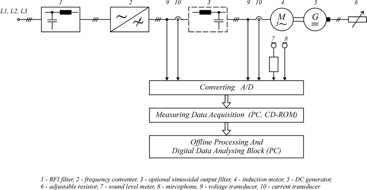
The block diagram of the laboratory drive and measurement systems
Dataset file
hexmd5(md5(part1)+md5(part2)+...)-{parts_count} where a single part of the file is 512 MB in size.Example script for calculation:
https://github.com/antespi/s3md5
File details
- License:
-
 open in new tab
CC BYAttribution
open in new tab
CC BYAttribution - Raw data:
- Data contained in dataset was not processed.
Details
- Year of publication:
- 2020
- Verification date:
- 2020-12-17
- Creation date:
- 2003
- Dataset language:
- English
- Fields of science:
-
- Automation, electronic and electrical engineering (Engineering and Technology)
- DOI:
- DOI ID 10.34808/zwtt-8763 open in new tab
- Verified by:
- Gdańsk University of Technology
Keywords
References
- dataset The AC motor voltage and audible noise waveforms in ship’s electrical drive systems with frequency converters
- publication Pomiar zakłóceń elektrycznych i hałasu okrętowego systemu napędowego z przemiennikami częstotliwości.
- publication The influence of frequency controlled ac drives on vibration and audible noise level on ships
- dataset The power spectral density of audible noise and electric disturbances in ship’s electrical drive systems with frequency converters
Cite as
Authors
seen 283 times