Search

Description
The dataset presents a result of measurements that are a part of electromagnetic field immunity tests. The radiated, radio frequency, immunity tests were carried out for a typical astable electronic multivibrator. Tests of immunity of electronic systems to radiated radio frequency (RF) disturbances in the frequency range from 80 MHz to 1 GHz are performed under the requirements specified in the electromagnetic compatibility (EMC) standards.
In laboratory conditions, the electromagnetic fields were simulated in the GTEM (Gigahertz Transverse Electromagnetic) cell (Fig. 1). An integrated signal generator, equipped with a built-in 45 W class A power amplifier module, was used in the measurement setup. The tested multivibrator was supplied from a battery of 9 V or externally from the NN DF1723003TC power supply. The signal cable connected to the input of an oscilloscope was led out of the tested PCB. The measurement process was controlled by the WIN 6000 software installed on a personal computer connected to the signal generator via the IEEE488 interface.
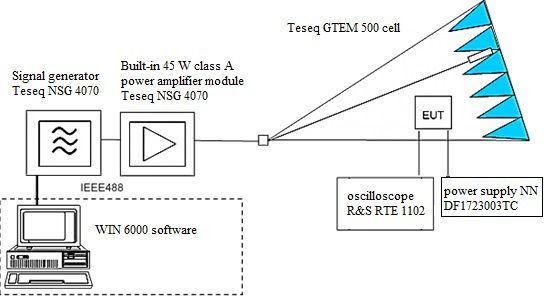
Figure 1. Configuration of the measuring system for testing the immunity of electronic systems
in the GTEM cell
A typical astable multivibrator built on bipolar transistors T3 and T4 was subjected to the immunity test (Fig. 2). The proper operation of the device is showed by flashing LEDs with variable frequency. A signal wire was led out from the collector of the transistor T3 and connected to the oscilloscope input. The system sensitivity to the radiated field in the GTEM cell was assessed based on the observation of the changes in the shape of the signal waveform controlling diode switching.
The normative test procedure was carried out in the frequency range starting at 80 MHz and incrementing in 1% steps up to at least 1 GHz. The RF signal was modulated with a sinusoidal signal with a frequency of 1 kHz and a modulation depth of 80%. Immunity tests were made for three different levels of the electromagnetic field strength 1 V/m, 3 V/m and 10 V/m, respectively. The position of the equipment under test in the uniform area of the GTEM cell was changed for three orthogonal orientations x, y, z (Fig. 3). During the measurements, on the oscilloscope, the differences in the shape of the voltage waveform to the reference waveforms recorded with the signal generator turned off were being observed.
The attached files contain oscillograms showing the voltage waveforms from the PCB that deviate the most from the reference waveform. For each case, information about the RF frequency of the signal generator is included in the file description.
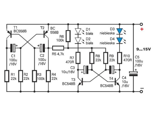
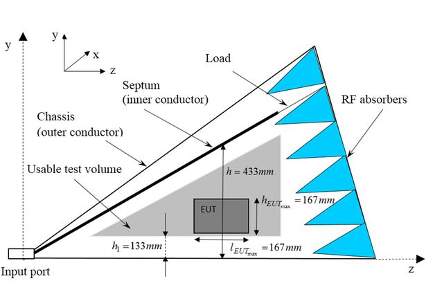
Figure 2. The electronic diagram of the AVT 720 system
Figure 3. The schematic diagram of a GTEM cell. Presented dimensions are for Teseq GTEM 500
Dataset file
hexmd5(md5(part1)+md5(part2)+...)-{parts_count} where a single part of the file is 512 MB in size.Example script for calculation:
https://github.com/antespi/s3md5
File details
- License:
-
 open in new tab
CC BYAttribution
open in new tab
CC BYAttribution
Details
- Year of publication:
- 2021
- Verification date:
- 2021-06-28
- Creation date:
- 2016
- Dataset language:
- English
- Fields of science:
-
- Automation, electronic and electrical engineering (Engineering and Technology)
- DOI:
- DOI ID 10.34808/1w2q-xp19 open in new tab
- Series:
- Verified by:
- Gdańsk University of Technology
Keywords
- electromagnetic field
- immunity test
- astable electronic multivibrator
- GTEM cell
- EMC
- radio frequency disturbances
References
- dataset The radiated immunity test of an astable multivibrator for various supply voltages
- dataset The radiated immunity test of an astable multivibrator at over-normative field strengths
- dataset The radiated immunity test of an astable multivibrator in the frequency range from 100 MHz to 300 MHz
Cite as
Authors
seen 159 times