Search
Selected results of signal measurements in a ship power station with two generators working in parallel with the use of the Estimator/Analyzer instrument

Description
The presented dataset is part of research focusing on the assessment of metrological properties of the instrument, Estimator/ Analyser (A/E v.2), developed and made at the Faculty of Electrical Engineering, Department of Marine Electrical Power Engineering, of Gdynia Maritime University. The instrument performs a set of measurement functions that allow the assessment of the electrical power quality parameters. The attached dataset contains the measurement results carried out in a laboratory, using the physical model of a ship power station.
The measurement setup is shown in Fig. 1.
The dataset file contains data recorded in a marine power plant at a sampling rate of 25.0 kHz and presents in seven columns the samples relating to the instantaneous values of three voltages on the main bars and four currents measured for two generators (G1 and G2), sequentially:
- samples related to the line voltage U12,
- samples related to the line voltage U23,
- samples related to the line voltage U31,
- samples related to the G1 generator current in phase 1 (IG11),
- samples related to the G1 generator current in phase 2 (IG12),
- samples related to the G2 generator current in phase 1 (IG21),
- samples related to the G2 generator current in phase 1 (IG22).
Voltage samples are expressed in V and samples relating to currents in mV.
To get the line voltage values from the respective samples, the voltage ratio of 150 [V/V] should be used.
To obtain the instantaneous values of the currents from the corresponding samples, the current probe ratio -20 [mV/A] must be used for the G1 generator samples, and -10 [mV/A] for the G2 generator (the “minus” sign means that the current flow direction has been corrected).
A measurement system based on NI PXIe-1062Q was used as a reference instrument.
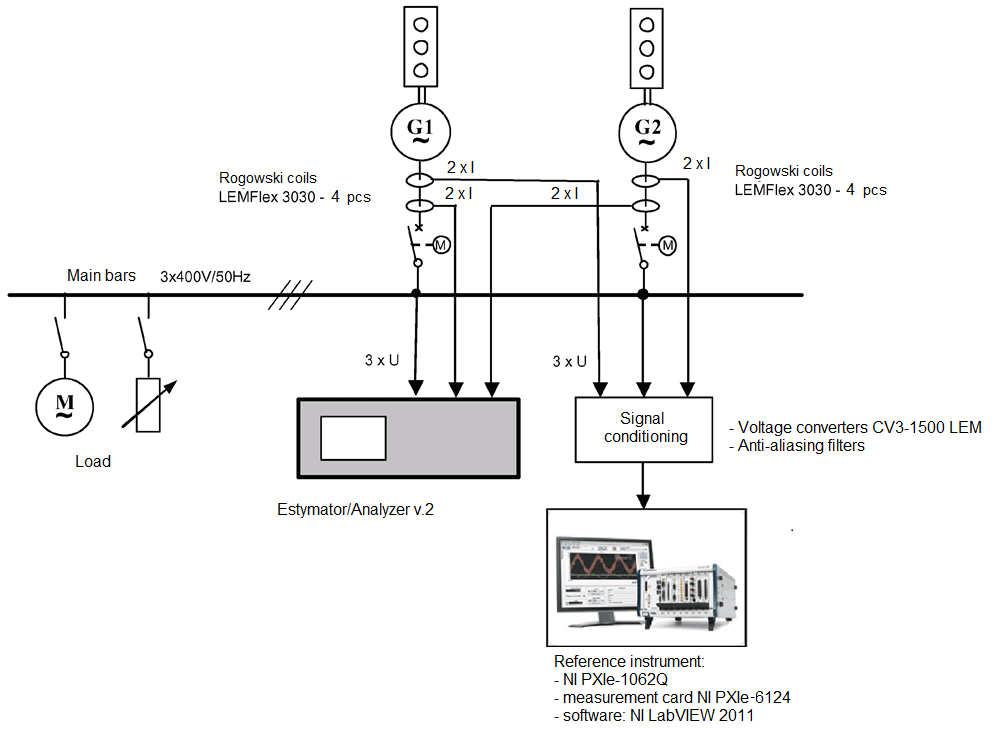
Fig. 1. The measurement setup
Dataset file
hexmd5(md5(part1)+md5(part2)+...)-{parts_count} where a single part of the file is 512 MB in size.Example script for calculation:
https://github.com/antespi/s3md5
File details
- License:
-
 open in new tab
CC BYAttribution
open in new tab
CC BYAttribution - Raw data:
- Data contained in dataset was not processed.
Details
- Year of publication:
- 2020
- Verification date:
- 2020-12-17
- Creation date:
- 2011
- Dataset language:
- English
- Fields of science:
-
- Automation, electronic and electrical engineering (Engineering and Technology)
- DOI:
- DOI ID 10.34808/dv88-sj58 open in new tab
- Verified by:
- Gdańsk University of Technology
Keywords
References
- dataset Measurements of the coefficients of current distribution between two generators operating in parallel in a ship power station
- dataset Measurements of the rms currents in two phases in a ship power station with two generators operating in parallel
- dataset Measurements of reactive power distribution in a ship power station with two generators working in parallel
- dataset Measurements of apparent power distribution in a ship power station with two generators working in parallel
- dataset Measurements of the coefficients of active power distribution between two generators operating in parallel in a ship power station
- dataset Measurements of the fundamental harmonic frequency of voltages on main bars in a ship power station
- dataset Selected results of measurements carried out in a ship power station with two generators working in parallel with the use of the NI PXIe-1062Q based measurement system
- dataset Measurements of active power distribution in a ship power station with two generators working in parallel
- dataset Measurements of active power coefficients in a ship power station with two generators working in parallel
- dataset Measurements of the rms voltages on main bars in a ship power station with two generators operating in parallel
Cite as
Authors
seen 224 times