Wyszukiwarka

Opis
The dataset contains the magnetic field measurement results that are part of a comprehensive study on the assessment of the magnetic field emissions onboard of the research-training vessel. The measurements were carried out, nearby the bow thruster motor fed from the inverter, during maneuvering and the sea voyage.
The bow thruster is assembled in the forepart of the ships’ hull and has constant pitch propeller. Using the control levers at the wings of the bridge, it is possible to change the speed and direction of the revolutions of the propeller, and in this way to move the bow of the ship during maneuvering. The bow thruster is driven with a squirrel cage asynchronous motor fed by the PWM frequency converter. The IGBT (Isolated Gate Bipolar Transistor) inverter was operating at 2 kHz (possible 4 kHz) switching frequency. The inverter output frequency was adjusted in the frequency range from 0 to 50 Hz. Measurements were performed in the bow thruster compartment with the ESM-100 H/E field meter, which was fixed on the wooden bar, about 1 m from the bow thruster motor (Figure 1).
Data recording of magnetic field emissions was carried out with a/d converters of the data acquisition board (DAQ), which were connected to the analog outputs of an isotropic field meter (Figure 2). ESM-100 H/E field meter, which was applied in this system, enables the measurements of a magnetic field induction in the measuring ranges from 1 nT to 20 mT. Four wide-band analog outputs of this meter afford possibilities for measuring the time waveforms of the magnetic fields, separately in the three orthogonal directions, in the output voltage range from 0 to 600 mV (see Table). The measured analog signal is conditioned with the use of National Instruments sub-assemblies. The initial conditioning follows and is realized through the low-pass filter module (for antialiasing application) with programmable cut-off frequency. The applied module has 8th-order elliptic filters, which provide a very sharp roll-off. Matching of the signal level to the a/d converter the DAQ input is realized by the input amplifier with the programmable gain. The formation of the output digital signal from the analog signal takes place in the a/d converter with a 16-bit resolution and sampling rate equal to 20 kS/s. Discrete signals are next analyzed (off-line) with the use of virtual instruments (LabVIEW software).
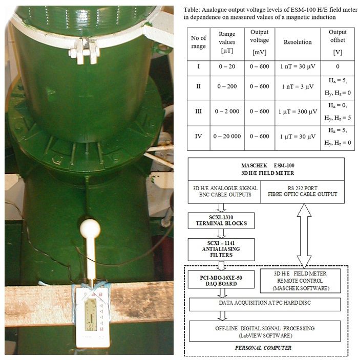
Figure 1. The ESM-100 H/E field meter located close to the bow thruster motor
Figure 2. A block diagram of the measuring system for assessment of magnetic field emissions
Plik z danymi badawczymi
hexmd5(md5(part1)+md5(part2)+...)-{parts_count} gdzie pojedyncza część pliku jest wielkości 512 MBPrzykładowy skrypt do wyliczenia:
https://github.com/antespi/s3md5
Informacje szczegółowe o pliku
- Licencja:
-
 otwiera się w nowej karcie
CC BYUznanie autorstwa
otwiera się w nowej karcie
CC BYUznanie autorstwa - Dane surowe:
- Dane zawarte w datasecie nie zostały w żaden sposób przetworzone.
Informacje szczegółowe
- Rok publikacji:
- 2020
- Data zatwierdzenia:
- 2020-12-17
- Data wytworzenia:
- 2007
- Język danych badawczych:
- angielski
- Dyscypliny:
-
- Automatyka, elektronika i elektrotechnika (Dziedzina nauk inżynieryjno-technicznych)
- DOI:
- Identyfikator DOI 10.34808/beh9-bq90 otwiera się w nowej karcie
- Weryfikacja:
- Politechnika Gdańska
Słowa kluczowe
- magnetic field emissions
- bow thruster motor
- IGBT inverter
- magnetic field induction
- magnetic field measurement
Powiązane zasoby
- dane badawcze The low-frequency magnetic field emissions on-board of the vessel
- publikacja Electromagnetic Field Measurements of Bow Thruster Drive with Frequency Converter
- publikacja Identification of Non-Stationary Magnetic Field Sources Using the Matching Pursuit Method
- publikacja Application of matching pursuit based method to identify sources of time-vary magnetic field
- publikacja A virtual instrument for the adaptive analysis of low-frequency magnetic-field emissions
- publikacja Zastosowanie adaptacyjnej dekompozycji sygnału do identyfikacji źródeł wolnozmiennego pola magnetycznego
- publikacja Spectral analysis of nonstationary low-frequency magnetic-field emissions from ship's power
Cytuj jako
Autorzy
wyświetlono 218 razy