Wyszukiwarka
Displacements of bones during bending test of first metatarsophalangeal joint after arthrodesis with medially or dorsally positioned locking plate and lag screw.

Opis
The Dataset contains the values of displacements of bone control points during the bending test of first metatarsophalangeal (MTP1) joint specimens after arthrodesis.
Three groups of samples were created depending on the MTP1 arthrodesis method:
-   group with medially positioned locking plate, samples P01-P02, P04-P07, P22;
-   group with dorsally positioned locking plate and lag screw, samples P08-P14;
-   group with medially positioned locking plate and lag screw, samples P15-P21.

The same short titanium locking plate (Medgal) and six 2.4 mm locking screws were used in all groups. The artificial models of metatarsal bone and proximal phalanx were created based on freely accessible STL geometry of the human foot (https://www.thingiverse.com/thing:22628). The geometry was scaled and cut to prepare bones for arthrodesis and fixation in dedicated steel jigs. The artificial bone models were additively manufactured with the fused filament fabrication (FFF) method using polylactide (PLA) material in Ultimaker 3 Extended 3D printer.
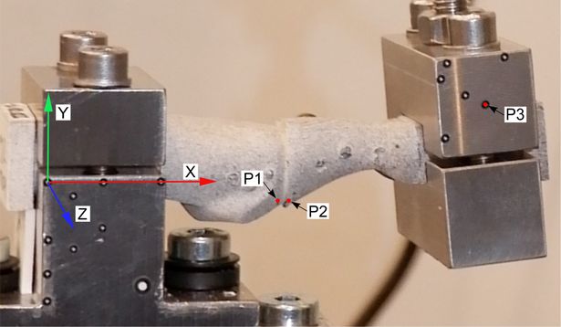
The bending test of total 21 samples was performed in a Zwick/Roell Z10 universal testing machine (UTM). The shaft of the metatarsal bone was clamped in stainless steel jig, while the“distal” end of the proximal phalanx was fixed in stainless steel clamp, which was connected to a traverse of UTM. A preload of 1 N and constant vertical displacement increment of 5 mm/min of the traverse were applied in the tests to simulate quasi static loading conditions. The tests were stopped after specimens failure. Digital image correlation (DIC) method and ARAMIS MC 3D 12M system were used to measure displacements at three control points P1, P2 and P3, see Figure. The displacements between points P1 and P2 allow to calculate the relative displacements between the bones.
The file has (.txt) extension and contains:
- the time of the test (in s, 1nd column);
- displacement in X direction of point P1 (in mm, 2nd column), P2 (in mm, 3rd column), P3 (in mm, 4rd column);
- displacement in Y direction of point P1 (in mm, 5th column), P2 (in mm, 6th column), P3 (in mm, 7th column);
- displacement in Z direction of point P1 (in mm, 8th column), P2 (in mm, 9th column), P3 (in mm, 10th column);
- force (in N, 11th column).
Plik z danymi badawczymi
hexmd5(md5(part1)+md5(part2)+...)-{parts_count} gdzie pojedyncza część pliku jest wielkości 512 MBPrzykładowy skrypt do wyliczenia:
https://github.com/antespi/s3md5
Informacje szczegółowe o pliku
- Licencja:
-
 otwiera się w nowej karcie
CC BYUznanie autorstwa
otwiera się w nowej karcie
CC BYUznanie autorstwa - Embargo na plik:
- 2023-12-31
- Dane surowe:
- Dane zawarte w datasecie nie zostały w żaden sposób przetworzone.
Informacje szczegółowe
- Rok publikacji:
- 2022
- Data zatwierdzenia:
- 2022-11-17
- Język danych badawczych:
- angielski
- DOI:
- Identyfikator DOI 10.34808/wqxn-8z65 otwiera się w nowej karcie
- Finansowanie:
- Weryfikacja:
- Politechnika Gdańska
Słowa kluczowe
Cytuj jako
Autorzy
wyświetlono 219 razy