Wyszukiwarka
The voltage on bus bars of the main switchboard of the ferry electrical power system during a layover at the port

Opis
The dataset is part of the research results on the quality of supply voltage on bus bars of the main switchboard of the ship's electrical power system in different states of ship exploitation. The attached dataset contains the measurement results carried out onboard the ferry during a layover at the port.
The ferry is equipped in a three-phase, three-wire electrical power system. The source of energy is three-phase synchronous generators driven by auxiliary diesel engines. Additionally, shaft generators driven by the propeller shaft of the main engine are used. The ship's electrical power plant consists of three free-standing generators of 1400 kVA each, and two shaft generators 1375 kVA each. The nominal voltage on bus bars of the main switchboard was 380 V with a frequency equal to 50 Hz. The free-standing generators have been the main energy source. The parallel operation of each shaft generator with the free-standing generators is possible, especially during a sea voyage with a calm wave surface. Additionally, each of the bow thrusters has been supplied of a single shaft generator, the most frequently, in configuration separated from the main electrical power system. The voltage of 220V has been obtained using a transformer.
The voltage waveforms on bus bars of the main switchboard were recorder with the digital measuring system, which allows the simultaneous measurement of three phase-to-phase or two-phase voltages. The initial conditioning of the input signals is carried out by optoisolation amplifiers and a low-pass filter module (antialiasing). The formation of the output digital signal from the analog signal takes place in the a/d converter with a resolution of 16 bits and a sampling rate of up to 20 kS/s. Using three channels at the same time allows the maximum sampling rate of 6.6 kS/s. The block diagram of the digital measuring system is shown in Figure.
The files contain voltage waveforms of the output of a/d converters in [V], in three phases for the 380 V network. The attenuation and offset of the measuring path for the 380 V network are equal to 134.0123 [V / V] and -0.0175 V, respectively. The sampling frequency is inserted in the first row of the attached file.
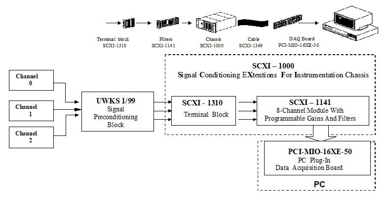
The block diagram of the digital measuring system
Plik z danymi badawczymi
hexmd5(md5(part1)+md5(part2)+...)-{parts_count} gdzie pojedyncza część pliku jest wielkości 512 MBPrzykładowy skrypt do wyliczenia:
https://github.com/antespi/s3md5
Informacje szczegółowe o pliku
- Licencja:
-
 otwiera się w nowej karcie
CC BYUznanie autorstwa
otwiera się w nowej karcie
CC BYUznanie autorstwa - Dane surowe:
- Dane zawarte w datasecie nie zostały w żaden sposób przetworzone.
Informacje szczegółowe
- Rok publikacji:
- 2020
- Data zatwierdzenia:
- 2020-12-17
- Data wytworzenia:
- 1999
- Język danych badawczych:
- angielski
- Dyscypliny:
-
- Automatyka, elektronika i elektrotechnika (Dziedzina nauk inżynieryjno-technicznych)
- DOI:
- Identyfikator DOI 10.34808/2hs6-3d49 otwiera się w nowej karcie
- Weryfikacja:
- Politechnika Gdańska
Słowa kluczowe
- quality of supply voltage
- bus bars main switchboard
- ship's electrical power system
- ferry
- electrical power plant
Powiązane zasoby
- dane badawcze The voltage on bus bars of the main switchboard of the ro-ro ship electrical power system during a sea voyage
- dane badawcze The voltage on bus bars of the main switchboard of the ro-ro ship electrical power system during a layover at the port
- dane badawcze The voltage on bus bars of the main switchboard of the ro-ro ship electrical power system during maneuvering
- dane badawcze The statistic properties of rms voltage and frequency in the ship's electrical power system
- dane badawcze The harmonic distortion of voltage waveforms in the ship's electrical power system
- dane badawcze The voltage on bus bars of the main switchboard of the ferry electrical power system during a sea voyage
- dane badawcze The voltage on bus bars of the main switchboard of the ferry electrical power system during maneuvering
Cytuj jako
Autorzy
wyświetlono 172 razy