Wyszukiwarka
The voltage on bus bars of the main switchboard of the ro-ro ship electrical power system during maneuvering

Opis
The dataset is part of the research results on the quality of supply voltage on bus bars of the main switchboard of the ship's electrical power system in different states of ship exploitation. The attached dataset contains the measurement results carried out onboard a ro-ro ship during maneuvering.
The ro-ro ship is equipped in three-phase, three-wire electrical power systems. The ship's electrical power plant consists of two free-standing generators 1000 kVA each and two-shaft generator 1500 kVA each (see Figure 1). The nominal voltage on bus bars of the main switchboard was 400 V with a frequency equal to 50 Hz. The voltage of 220V has been obtained by means of a transformer.
During the maneuvering and re-loading operations, the two free-standing generators G1 and G2 have been used. The single shaft generator has been used during sea voyage as well as during maneuvering as an energy source of a bow thruster. The each of shaft generators could not work in parallel with other electrical energy sources, excluding short switching time (roughly 2 seconds). The shaft generators have been connected with the remaining system only with the help of a simple circuit breaker. It has been possible thanks to adjusting screw propellers using.
The voltage waveforms on bus bars of the main switchboard were recorder with the digital measuring system, which allows the simultaneous measurement of three phase-to-phase or two-phase voltages. The initial conditioning of the input signals is carried out by optoisolation amplifiers and a low-pass filter module (antialiasing). The formation of the output digital signal from the analog signal takes place in the a/d converter with a resolution of 16 bits and a sampling rate of up to 20 kS/s. Using three channels at the same time allows the maximum sampling rate of 6.6 kS/s. The block diagram of the digital measuring system is shown in Figure 2.
The files contain voltage waveforms of the output of a/d converters in [V], in three phases for 400 V and 220V networks. The attenuation and offset of the measuring path for the 220 V network are 77.6398 [V/V] and -0.017 V, respectively. For the 400 V network, the attenuation and offset of the measuring path are equal to 134.0123 [V / V] and -0.0175 V, respectively. The sampling frequency is inserted in the first row of the attached files.
The files are described as follows: ro-ro_maneuvering_the value of the mains voltage (400 or 220)_number of the set. The file named ro_ro_prepare_maneuvering_400.TXT contains measurement data that was recorded during preparation for maneuvering.
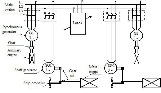
Figure 1. The electrical power plant configuration on the ro-ro ship
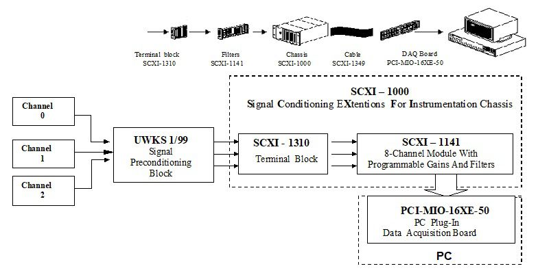
Figure 2. The block diagram of the digital measuring system
Plik z danymi badawczymi
hexmd5(md5(part1)+md5(part2)+...)-{parts_count} gdzie pojedyncza część pliku jest wielkości 512 MBPrzykładowy skrypt do wyliczenia:
https://github.com/antespi/s3md5
Informacje szczegółowe o pliku
- Licencja:
-
 otwiera się w nowej karcie
CC BYUznanie autorstwa
otwiera się w nowej karcie
CC BYUznanie autorstwa - Dane surowe:
- Dane zawarte w datasecie nie zostały w żaden sposób przetworzone.
Informacje szczegółowe
- Rok publikacji:
- 2020
- Data zatwierdzenia:
- 2020-12-17
- Data wytworzenia:
- 1999
- Język danych badawczych:
- angielski
- Dyscypliny:
-
- Automatyka, elektronika i elektrotechnika (Dziedzina nauk inżynieryjno-technicznych)
- DOI:
- Identyfikator DOI 10.34808/dcfx-h357 otwiera się w nowej karcie
- Weryfikacja:
- Politechnika Gdańska
Słowa kluczowe
- quality of supply voltage
- the bus bars main switchboard
- ship's electrical power system
- ro-ro ship
- electrical power plant
Powiązane zasoby
- dane badawcze The voltage on bus bars of the main switchboard of the ro-ro ship electrical power system during a sea voyage
- dane badawcze The statistic properties of rms voltage and frequency in the ship's electrical power system
- dane badawcze The harmonic distortion of voltage waveforms in the ship's electrical power system
- dane badawcze The voltage on bus bars of the main switchboard of the ro-ro ship electrical power system during a layover at the port
- dane badawcze The voltage on bus bars of the main switchboard of the car carrier electrical power system at sea trials during maneuvering
- dane badawcze The voltage on bus bars of the main switchboard of the ferry electrical power system during a layover at the port
Cytuj jako
Autorzy
wyświetlono 382 razy